Digital Power Supply Wiring Diagram Governor 25+ Images Result
Digital Power Supply Wiring Diagram Governor. Which requires separate power sources for the dl405 system, input devices, and output loads. Each part ought to be set and linked to other parts in specific manner.
Many ideas of 12v and 5v dual power supply circuit diagram at 3a max; • use #18 wire minimum; Both units have the same power supply requirements, vibration capability, and system response.
hi lo wiring diagram jeep patriot fuse panel diagram 1978 ford f 250 heater fan wiring diagram wiring diagram for a 1981 camaro
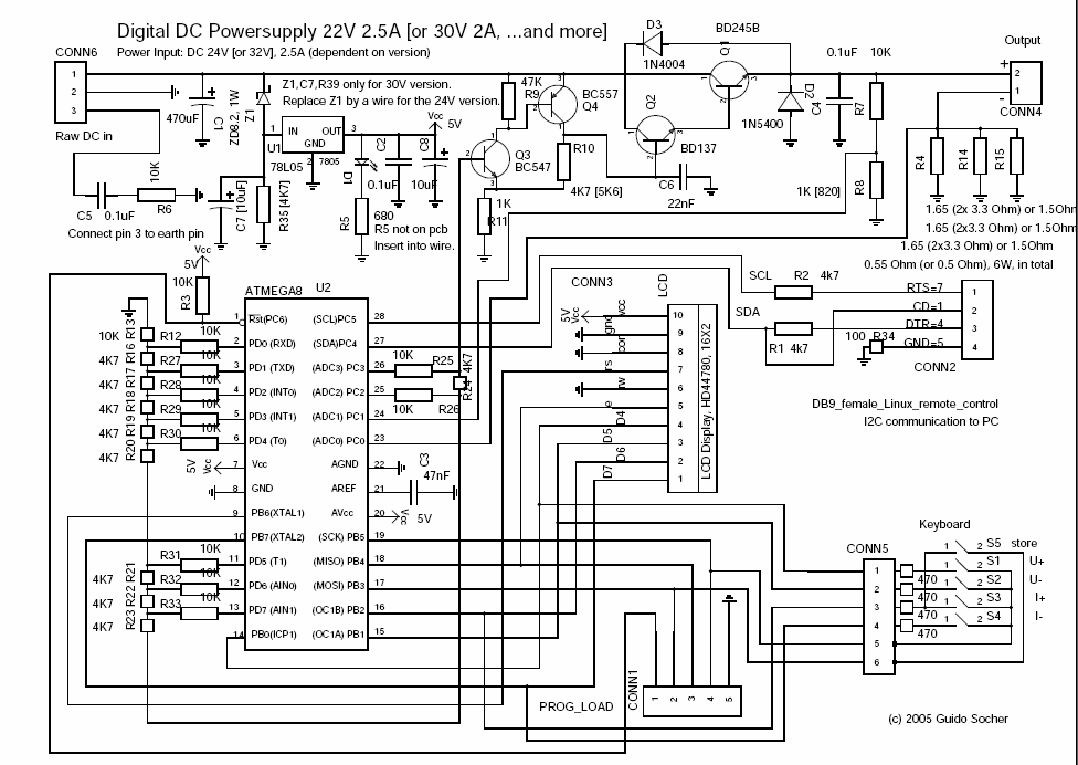
Explain this circuit Digital linear PSU Electronics Forums
Otherwise, the arrangement won’t work as it ought to be. Red wire is power supply wire for the meter and also signal wire of voltage measurement (ensure voltage between red and black wire. • use #18 wire minimum; Power tap used with bafcon only.

Source: pinterest.com
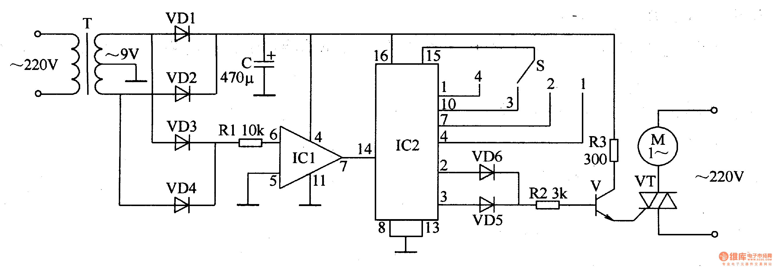
It is used to alert you to potential A lot of 6v supply diagrams; The sheet metal box is designed for skid or control box mounted applications in an additional enclosure for protection from the elements. The black wire is the common wire or ground wire. This circuit diagram is given below.

Source: eleccircuit.com
The sheet metal box is designed for skid or control box mounted applications in an additional enclosure for protection from the elements. Each part ought to be set and linked to other parts in specific manner. You can also follow the wiring instruction: The new 24 pin connector added one line apiece for ground, 3.3, 5, and 12 volts. 5v.

Source: picmicrolab.com
Lighting governor schematic circuit diagram. The black wire is the common wire or ground wire. Otherwise, the arrangement won’t work as it ought to be. Not compatible with any other controller. Refer to the section below re isolated meter power and wiring diagram 1 at the end of this article.

Source: pinterest.com
Red wire is power supply wire for the meter and also signal wire of voltage measurement (ensure voltage between red and black wire. 0 27 1 minute read. Actual component layout may differ from. Wiring diagrams 2 and 3 at the end of this article. The 24 pin connector is polarized so it can only be plugged in pointing in.

Source: linuxfocus.org
12v 350 watt power supplies are very common when using various light controller boards (sandevices, falcon16, lor cmb24d, etc.). Refer to figure 1 for pin functionality. The following information is important for a good installation. Lighting governor schematic circuit diagram. Not compatible with any other controller.

Source: circuit-diagramz.com
This pin is simply a + battery supply for the speed select switches. The 24 pin connector is polarized so it can only be plugged in pointing in the correct direction. 5v to 8v dc converter power supply circuit diagram. If governor is to be switched through the ignition switch, run power to the governor directly via a dedicated #16.

Source: pinterest.es
Each part ought to be set and linked to other parts in specific manner. The new 24 pin connector added one line apiece for ground, 3.3, 5, and 12 volts. 0 27 1 minute read. 12v 350 watt power supplies are very common when using various light controller boards (sandevices, falcon16, lor cmb24d, etc.). General information description the woodward 2301d.

Source: circuit-diagramz.com
Check that the wiring from the switch to the battery is at least #14 gage. The new 24 pin connector added one line apiece for ground, 3.3, 5, and 12 volts. Proact digital plus manual 26112 iv woodward warnings and notices important definitions this is the safety alert symbol. 24v to 220v 1000w dc ac sine wave inverter for photovoltaic.

Source: circuitdiagram.net
Red wire is power supply wire for the meter and also signal wire of voltage measurement (ensure voltage between red and black wire. If governor is to be switched through the ignition switch, run power to the governor directly via a dedicated #16 wire. General information description the woodward 2301d controls load sharing and speed of generators driven by diesel.

Source: bestengineeringprojects.com
General information description the woodward 2301d controls load sharing and speed of generators driven by diesel or gaseous engines. Refer to the section below re isolated meter power and wiring diagram 1 at the end of this article. The black wire is the common wire or ground wire. 12v to 24v dc converter power supply circuit diagram. Where the load.

Source: rajuaji8.blogspot.com
The motor could be replaced with a 12 v spring loaded solenoid the design. The circuit of a diesel engine speed governor or controller can be seen in the above figure using a feedback rpm processor or a tachometer circuit. Check that the wiring from the switch to the battery is at least #14 gage. Timeline so people could appreciate.

Source: schematics.com
This pin is simply a + battery supply for the speed select switches. Be sure to use cable shieldings and power supply connections meeting. A switch mode power supply. The main supply of 220v is fed directly to the centre tapped transformer. Which requires separate power sources for the dl405 system, input devices, and output loads.

Source: picmicrolab.com
This video does a quick walk. Timeline so people could appreciate just how long it took to get to where we are today. 5v to 8v dc converter power supply circuit diagram. The new 24 pin connector added one line apiece for ground, 3.3, 5, and 12 volts. Keep all wiring to the governor as short as is practical.

Source: electronicsforu.com
The left side ic1 555 stage forms a simple tachometer circuit which is configured with a hall effect sensor attached. 0 27 1 minute read. Be sure to use cable shieldings and power supply connections meeting. Each part ought to be set and linked to other parts in specific manner. It is used to alert you to potential

Source: seekic.com
Refer to figure 1 for pin functionality. Not compatible with any other controller. A particular circuit ensures that only the current of the control. • if governor power is to be switched through the ignition switch, run power to the governor directly via a dedicated #16 wire. Power tap used with bafcon only.
![[DIAGRAM] Digital Power Supply Wiring Diagram Governor [DIAGRAM] Digital Power Supply Wiring Diagram Governor](https://i.pinimg.com/736x/70/e6/7f/70e67f3fb44ab6e685ef0af688a77800.jpg)
Source: diagramcloud.blogspot.com
To some the term digital power supply may loosely refer to a power supply that uses switching technology, i.e. It is almost always the case that identical supplies are used when connecting them in parallel due to the challenges of efficiently configuring the. Check that the wiring from the battery to Hi, please check the image. This circuit diagram is.

Source: electronics-lab.com
Not compatible with any other controller. Red wire is power supply wire for the meter and also signal wire of voltage measurement (ensure voltage between red and black wire. Timeline so people could appreciate just how long it took to get to where we are today. • if governor power is to be switched through the ignition switch, run power.

Source: electronicspoint.com
This circuit diagram is given below. Be sure to use cable shieldings and power supply connections meeting. Actual component layout may differ from. A significant advantage of this circuit is that the circuit draws almost no current when in the. The left side ic1 555 stage forms a simple tachometer circuit which is configured with a hall effect sensor attached.

Source: circuitdiagram.net
This circuit diagram is given below. Actual component layout may differ from. The left side ic1 555 stage forms a simple tachometer circuit which is configured with a hall effect sensor attached. General information description the woodward 2301d controls load sharing and speed of generators driven by diesel or gaseous engines. Which requires separate power sources for the dl405 system,.

Source: new.linuxfocus.org
• use #18 wire minimum; It is almost always the case that identical supplies are used when connecting them in parallel due to the challenges of efficiently configuring the. Wiring diagrams 2 and 3 at the end of this article. The load current distribution is dependent upon both the design of the power supplies and the design of the external.